|

|
|
|||
|
Illustrations
 Slow sand filter drawing Note:In addition to smaller gravel (1/4 inch instead of 3/8 inch), a 2 inch layer of coarse sand is recommended immediately on top of the 1/4 inch pea gravel. New illustration: The addtion of a float valve makes the filter more convenient to operate and does not require electricty or petrol to operate. |
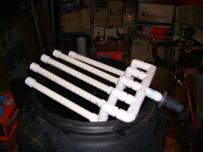 This is the drainpipe assembly with the caps installed. It is just sitting on top of the container for the sake of taking the picture. The output of the drainpipe assembly is hooked to a "bulkhead fitting" sometimes called a "bulkhead adapter". This keeps the output pipe from leaking where it passes through the filter container. |
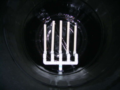 This is how the drain pipes look when they are installed in the container. This container is 40 inches deep. |
 There is a short piece of 1/2 inch pvc that hooks this up to the baffle assembly. |
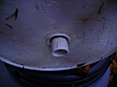
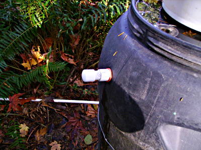
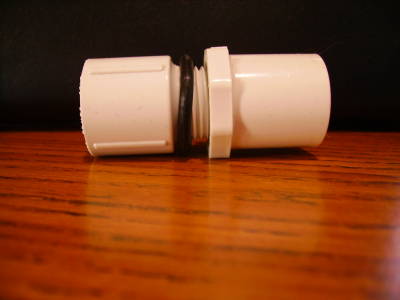 This is a close-up of the threaded bushing and threaded male adapter. Only 1 o ring is shown but 2 are needed - one on the inside of the bucket and one on the outside of the bucket. |
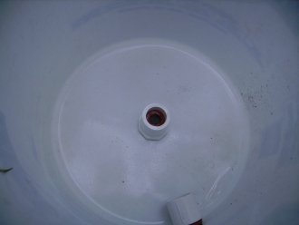 A 3/4 inch spade bit was used to drill a hole in the bottom of the bucket. The male adapter and threaded bushing were then installed with a number 16 o ring on each side of the bucket. The adapter and bushing are 1/2 inch. |
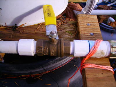 This ball valve is used to set the flow to the same rate as the output of the filter. |
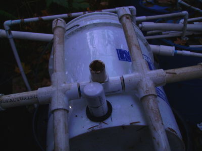
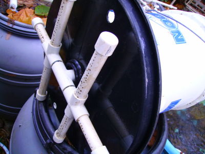 The container used for the filter came with a top with 1 hole in the center. Another "vent" hole was added on each side to allow air (oxygen) to circulate through to the water in the filter. The "vent" holes are covered by screens. This illustration shows the baffle pipes hooked up through the top. They are just "friction-fit" into the adapter that has been installed in the bottom of the bucket. The small holes in the baffle pipes are drilled with a number 50 drill bit. They allow the water to slowly flow into the filter. This keeps the surface of the sand and the biofilm from being disturbed. |
 This is the drain that was added to allow the wet-harrowing water to drain off. Note the screen in the vent hole on top of the lid near the bottom of the bucket. The hole for this screen was drilled with a 3/4 inch spade bit. |
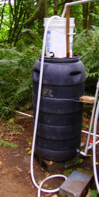 The completed filter hooked up to the automatic recirculating pump. Please note:This is not a "production" model and is not intended to be aesthetically pleasing - it is strictly funtional. |
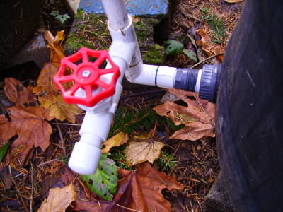 Open this valve to allow water to flow through the filter rapidly to wash the sand. Keep in mind that this valve, if open all the way, will let water flow through the filter too fast for purification. back to faq page 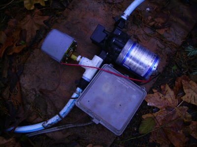 This is the pump used to recirculate the water. It runs on 12 volts dc. supplied by a 12 volt deep cycle battery The pressure switch was added for dependabiltiy and pressure adjustment flexibilty. The flow is controlled by the ball valve shown above. DANGER! do not use a 120 volt ac motor in this fashion. This motor is outdoors under cover but still not safe with 120 volt operations (either ac or dc). The surrounding area is usually wet which adds to the conductivity greatly increasing the likelyhood of a dangerous shock. Although a fuse will not protect against electricial shocks, it will keep a short or overload from causing extensive damage. Always, ALWAYS, use a fuse of appropriate amperage in your circuit. Keep in mind, that if you are using a battery charger that runs on 110 volts ac on your battery, you are effectively connected to 110 volts ac. If the battery charger transformer or circuit, gets wet or shorts out, there could likely be 110 volts at the motor with enough current to create a hazardous condition without blowing the dc fuse. Consult a licensed electrician before you hook this up. You have been warned! |
|
|
 This is the baffle before cleaning. Note the small piece of 1/2 inch pvc at the center. That is how it connects to the bucket through the top. It just frictions in. It won't matter if it leaks slightly because the water will end up in the filter as it flows through the air vent. |

This work is licensed under a Creative Commons Attribution-Noncommercial-Share Alike 3.0. terms of use